Page
Magnify
This control provides the option to apply horizontal gain of *6 or *8, (depending on
standard), and vertical gain of *1, *2, *5 and *10. If vertical gain is applied, it is possible
to scroll the waveform window to see the rest of the waveform.
Using Magnify affects the vectorscope view, as vectors are always produced based on
the data being shown in the waveforms.
This control can also be changed from the main toolbar.
The level of magnification is indicated in the top right of the waveform graticule.
TRS Pass
By default, TRS data is not displayed in the mini-pic, waveform view, or vectorscope.
This control lets you enable the display of TRS. The data shown in the dataview will
always contain any TRS data present on the signal, regardless of the state of this control.
This control can also be changed from the main toolbar.
Audio Group A PPM, Audio Group B PPM
The audio PPM display can show two audio groups. These controls let you select which
two audio channels of the four that can be used, to display on the meters.
Delay Measurement (only if Advanced Option package is present)
This setting opens the delay measurement dialogue box. The timings displayed in this
dialogue are only valid if the system has been configured in the correct mode. For full
details on how to use this mode, refer to Appendix A3 Measuring Audio/Video Delays.
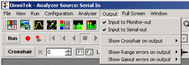
Output Menu
This menu controls features relating to the output video.
OmniView can display a crosshair on the output. The crosshair is always centred over
the sample currently displayed in the dataview. The crosshair can appear on the
analogue (monitoring) output, or the serial digital output, or on both outputs.
OmniView can detect when the incoming video is out of range, based on the range
thresholds set up in the Engineering menu (see page 16 for details), and key out any
erroneous pixels and replace them with a flashing black and white pattern. This error
display can be included on the analogue output, the digital output, or both outputs. The
menu selection determines which output is used to display the flashing pattern. Note that
range errors can also be highlighted onto the YUV waveforms. The same thresholds are
used to determine out of range, but the choice of highlighting is set on the Options/Data
menu, from within the waveform window.
Similarly, OmniView can detect when the incoming video (YUV data) is outside of valid
RGB colour space. Again out of gamut pixels can be highlighted on either output with the
flashing pattern. In the same way, out of gamut pixels can also be shown on the RGB
waveforms. Note it is not possible to highlight pixels with range errors and pixels with
gamut errors simultaneously on the waveforms, as pixels with range errors can only be
seen when displaying YUV waveforms, and pixels with gamut errors can only be seen
when displaying RGB waveforms.


