1
1.1 About the PC1616/PC1832/PC1864 System
This product is in conformity with EMC Directive 89/336/EEC
based on results using harmonized standards in accordance
with article 10(5), R&TTE Directive 1999/5/EC based on follow-
ing Annex III of the directive and LVD Directive 73/23/EEC as
amended by 93/68/EEC based on results using harmonized
standards.
This product meets the requirements of Class II, Grade 2 equip-
ment as per EN 50131-1:2004 Standard. This product is suit-
able for use in systems with the following notification options:
• A (use of two warning devices and internal dialer
required),
• B (self powered warning device and internal dialer
required),
• D (use of DSC model T-Link TL250 encrypted Ethernet
communicator required).
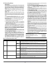
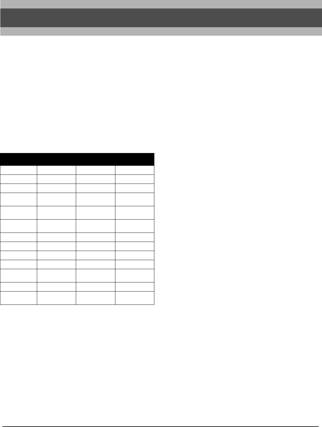
The PC1616/PC1832/PC1864 are high end security sys-
tems. Below are the list of features for each panel:
The LCD keypad guides users through their available
options with easy-to-understand prompts.
The status of the PC1616/PC1832/PC1864 system can be
monitored over telephone lines, or using an alternative com-
municating device, including Skyroute™, T-LINK, GS-3050
and DVACS.
You can program the PC1616/PC1832/PC1864 using any
system keypad, or using DLS downloading software and a
computer (see section 3, ‘How to Program’).
Review the complete manual set before installing the
PC1616/PC1832/PC1864 security system.
1.2 About the PC1616/PC1832/PC1864 Manual Set
Reference Manual
This manual provides:
• An overview of the system (Section 1: “Introduction”)
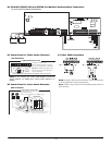
• How to install and wire the system and its modules (Sec-
tion 2: “Installation and Wiring”)
• How to program the system (Section 3: “How to Pro-
gram”)
• An introduction to the user interface and keypad opera-
tion (Section 4: “Keypad Commands”)
• An overview of the main system programming sections
(Section 5: “Programming Sections”).
Installation Guide
The Installation Guide provides the basic installation, wiring
and programming information required to program the Pow-
erSeries PC1616, PC1832 and PC1864 control panels.
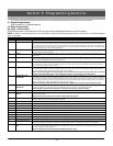
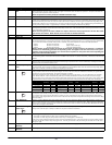
Programming Worksheets
The Programming Worksheets provid a detailed list of all
programming sections available in the panel and a place to
record your programming. Be sure to record all your system
programming in the Programming Worksheets. If adding
modules to your PowerSeries Control Panel, refer to the
Installation Instructions that come with each module.
User Guide
One user guide comes with the PC1616/PC1832/PC1864
system. The User’s Guide provides easy to follow instruc-
tions for end users. Installers should also review this manual,
in order to properly instruct the end-users once the installa-
tion is complete.
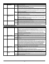
1.3 Control and Indicating Equipment Specifications
Zone Configuration
• 6 Fully programmable zones (PC1616)
• 8 Fully programmable zones (PC1832/PC1864)
• 34 zone types, 9 programmable zone attributes
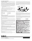
• Zone configurations available: Normally closed, Single
EOL and Double EOL zone supervision
• Hardwired zone expansion (fully supervised) available
using the Model PC5108 (eight Zone Expander Module)
and the Model PC5700 (Fire Module)
• Expandable to 16 zones (PC1616)
• Expandable to 32 zones (PC1832)
• Expandable to 64 zones (PC1864)
• One zone input available on the keypads
• Wireless zone expansion (fully supervised) available
using the Model PC5132 (RF Receiver, operating at
433MHz)
NOTE:
PC1616 expandable to 16 zones only.
• Up to 2 partitions (PC1616)
• Up to 4 partitions (PC1832)
• Up to 8 partitions (PC1864)
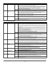
Access Codes
• 39 access codes:
• 32 User Codes (Level 2)
• 1 System Master Code (Level 3)
• 2 Supervisor Codes
• 2 Duress Codes
• 1 Maintenance/Guard Code
• 1 Installer Code (Level 3)
• Programmable attributes for each user code (see sec-
tion 4.2 for details)
• 1,000,000 access code variations (using 6-digit codes)
• Duress codes derived from user codes plus 1 digit are
not allowed
Section 1: Introduction
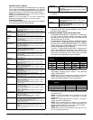
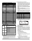
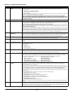
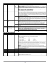
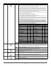
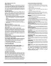
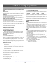
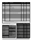
PC1616 PC1832 PC1864
On-board Zones 6 8 8
Hardwired Zones 16 (1xPC5108) 32(3xPC5108) 64 (7xPC5108)
Wireless Zones 16 32 32
Keypad Zone
Support
888
On-board PGM
Outputs
PGM 1 - 50mA
PGM 2 - 300mA
PGM 1 - 50mA
PGM 2 - 300mA
PGM 1/3/4 - 50mA
PGM 2 - 300mA
Additional PGM
Outputs
PC5208
- 8x50mA
PC5204 - 4x500mA
PC5208 - 8x50mA
PC5204 - 4x500mA
PC5208 - 8x50mA
PC5204 - 4x500mA
Keypads 8 8 8
Partitions 2 4 8
User Codes 32 + Master Codes 32 + Master Codes 32 + Master Codes
Event Buffer 500 Events 500 Events 500 Events
Transformer
Required
16.5VAC
40VA
16.5VAC
40VA
16.5VAC
40VA
Battery Required 4Ah / 7Ah / 14Ah 4Ah / 7Ah / 14Ah 4Ah / 7Ah / 14Ah
Bell Output
12V 700 mA
(continuous)
12V 700 mA
(continuous)
12V 700 mA
(continuous)
WWW.DIYALARMFORUM.COM