52
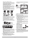
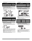
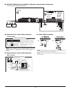
Two-Wire Smoke Detector Zones
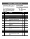
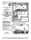
PGM2 can be programmed for 2-wire smoke detectors. More
than one smoke detector can be connected in parallel, refer
to the Compatability Chart in this manual for details (see
Appendix B, diagram B.1). PGM2 must be programmed for
2-wire smoke support (PGM2 only) Option[4]. Refer to the
PC1616/PC1832/PC1864 Programming Worksheets, ‘Pro-
grammable Output Options’.
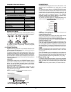
Fire Supervisory Zone
This zone is always an end of line resistor type with normally
open alarm contacts from the Fire Supervisory initiating
devices. A maximum of 20 Fire Supervisory devices can be
connected in parallel on a single zone. The zone wiring is
supervised by the control panel for:
• Short Circuit - Supervisory off-normal
• Open Circuit - loss of the end of line resistor; this will be
indicated as a Zone Trouble
A Fire Supervisory zone monitors fire critical systems to indi-
cate when those systems are in a condition that could pre-
vent normal operation. These most commonly monitored
devices are sprinkler gate valves to ensure they are not
closed, which would prevent water from flowing to the sprin-
klers.
6.3 Fire System Operation
Manual Signal Silence
Once the panel is in alarm and the alarm notification appli-
ances are active, entering a valid user code will silence the
alarm signals.
Silencing will not deactivate any output programmed as Fire
Strobe.
Manual Silencing initiates a Trouble condition by turning on
the keypad Trouble LED and sounding the keypad buzzer.
The buzzer may be silenced by entering an access code.
Automatic Signal Silence (Bell Time-out)
Ref: Section[014] Option [8] Fire Bell Follows Time-out
Ref: Section[005] Bell Time-out (default 004 minutes)
The fire alarm notification appliances may be set to silence
automatically after a programmed time. The system is
default programmed to silence the notification appliances
four minutes after the last initiated fire alarm. If the Fire Time-
out option is disabled, the notification appliance can only be
silenced manually.
The Bell Time-out timer begins upon the first fire alarm. Each
subsequent alarm will restart the timer.
Manual Sensor Reset ([*][7][2])
The Sensor Reset function is designed so that the user can
manually reset latching smoke detectors by entering [*][7][2].
In order for this feature to function, the detectors to be reset
must be connected to a programmable output (PGM1-4,
AUX+).
Program the output as ‘Sensor Reset 2’ (PGM output option
#03). The output pulse time is by default set at five seconds.
For instructions on output programming, see your
PC5020CF Installation Manual, Section 5.3 ‘Basic Program-
ming’, [009]-[011] Programmable Output Options.
RECOMMENDED: As a security measure, ensure that a code
is required to activate [*][7][2]. This will require that a user
enter a valid access code after entering [*][7][2] in order to
reset smoke detectors.
Subsequent Alarm Operation
If the alarm notification appliances have been silenced –
manually or automatically – and a subsequent fire alarm is
initiated, the following will occur:
• Audible and visual notification appliances will activate as
programmed.
• The Bell Time-out, if used, will restart for a full timing
period before automatic silencing.
• The new alarm and all previous alarms/troubles will be
displayed.
If a subsequent Fire alarm is initiated before the alarm notifi-
cation appliances have been silenced, either manually or
automatically, then the following will occur:
• The Bell Time-out, if used, will restart for a full timing
period before automatic silencing.
• The new alarm will be shown.
Auto-Scroll LCD Keypad Display
When an alarm is initiated, the Alarm and selected Trouble
conditions will be displayed on the system LCD keypad(s). If
there is more than one Alarm or Trouble present simulta-
neously, the keypad will continuously scroll through each
event. Items on the scroll list are displayed at two-second
intervals. The keypad will beep as each message is dis-
played.
Although critical Troubles are displayed, Auto-scroll is only ini-
tiated upon a Fire Alarm. If a Fire Trouble is detected and a
Fire Alarm is not present, the Trouble will be indicated as any
other system trouble; the keypad Trouble light will turn on and
the keypad buzzer will beep.
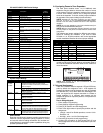
The following events are included in the Auto-scroll.
•’Fire Alarm [Zone Label]’: This message will appear for
all Fire Alarms. Messages are displayed sequentially by
zone number.
•’Fire Trouble [Zone Label]’: This message will appear for
Fire off-normal conditions only and the keypad buzzer will
beep once as it is displayed. Messages are displayed
sequentially by zone number.
•’Bell CCT Trouble’: This message will appear if an open
fault is detected on the PC1616/PC1832/PC1864 bell
zone.
•’Failure to Communicate’: This message will appear
when the panel cannot report to the central station.
Auto-scroll will stop when a valid user code is entered to
silence the alarm notification appliances.
Fire Trouble Conditions
In all cases, when the panel detects a Trouble condition, the
keypad Trouble light turns on and the keypad buzzer will
sound two short beeps every 10 seconds. Pressing any key
will silence the audible Trouble signal. The Trouble buzzer will
resound if another Trouble is generated.
Fire Zone Trouble
A fire zone Trouble will be generated when an open circuit is
detected on any fire zone.
AC Trouble
An AC Fail Trouble is generated if the AC fails on the
PC1616/PC1832/PC1864. AC Troubles are grouped for
common indication on a remote annunciator as an ‘AC Trou-
ble’.
See also Section 5.6 ‘Communicator Programming’, [377]’
Communication Variables.
Battery Trouble
A battery Trouble is generated if the PC1616/PC1832/
PC1864/PS5350 panel batteries are open or shorted. This
Trouble condition only turns on the keypad Trouble light and
sounds the keypad buzzer.
WWW.DIYALARMFORUM.COM