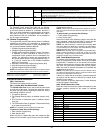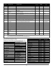
60
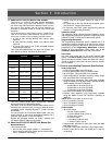
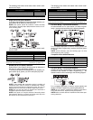
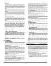
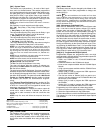
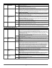
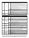
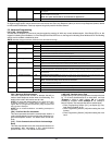
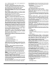
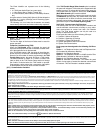
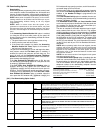
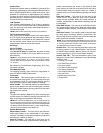
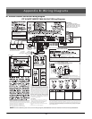
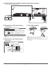
B.3 PC1616/PC1832/PC1864 European Wiring Diagram
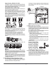
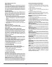
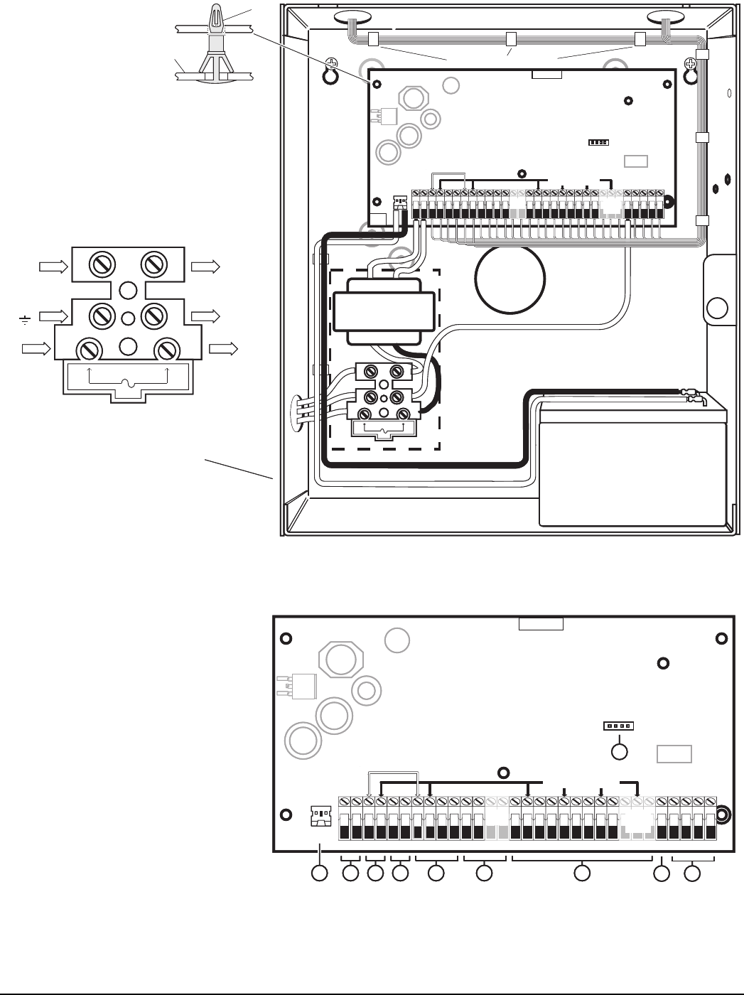
CON1
BAT+BAT-
1.Insert Stand off into cabinet
mounting hole in the desired location.
Snap-in-place.
2.Position circuit board mounting holes
over standoffs. Press firmly on board
to snap-in-place.
IMPORTANT!
Minimum 1/4" (6.4mm) separation
must be maintained at all points between
BATTERY/AC WIRING and all other
wiring connections
FUSE
TB-2
AC AC RED BLK YEL GRN Z1 COM Z2 Z3 COM Z4 Z5 COM Z6 Z7 COM Z8
AUX+ BELL+
AUX- BELL-
PGM1 PGM3
EGND
TIP T-1
PGM2 PGM4
RING R-1
DSC
REV XX
220
UA503
PC-LINK
No.14AWGor smallerconductor
Tye Wraps(not supplied)recommended
InternallyConnected
PC1864
Only
PC1864
PC1832
Only
PC1616/1832/1864
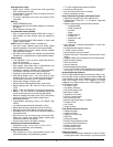
AC in
(Line)
AC in
(Neut)
Transformer
(Neut)
Transformer
(Line)
To EGND on
Control Module
PE
FUSE
PC Board
Cabinet
Stand Off
98431
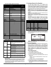
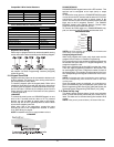
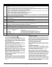
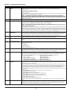
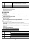
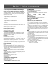
5
2
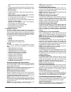
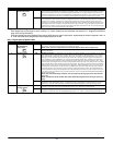
TB-2
AC AC RED BLKYEL GRN Z1 COM Z2 Z3 COM Z4 Z5 COM Z6 Z7 COM Z8
AUX+ BELL+
AUX- BELL-
PGM1 PGM3
EGND
TIP T-1
PGM2 PGM4
RING R-1
DSC
REV XX
220
UA503
CON1
BAT+BAT-
PC-LINK
Internally Connected
AUX+ and Keybus (Red) areInternally Connected
Total current draw from Keypads, PGMOutputs and
Aux circuits must notexceed 500ma
PC1864
Only
PC1864
PC1832
Only
6
PC1616/1832/1864
10
16.5V /40VA
AC
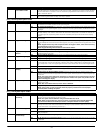
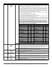
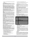
IMPORTANT:
1.This equipment, Alarm Controller PC1616/1832/1864/ETC shall
be installed and used within an environment that provides the
pollution degree max 2 and overvoltages category II
NON HAZARDOUS LOCATIONS, indoor only.The equipment is
FIXED and PERMANENTLY CONNECTED and is designed to be
installed by service persons only; [service person is defined as a
person having the appropriate technical training and experience
necessary to be aware of hazards to which that person may be
exposed in performing a task and of measures to minimize the risks
to that person or other persons.]
2.The connection to the mains supply must be made as per the local
authorities rules and regulations: In the UK as per BS6701.
An appropriate disconnect device must be provided as part of the
building installation.Where it is not possible to rely on identification of
the NEUTRAL in the AC MAINS SUPPLY, the disconnecting device
must disconnect both poles simultaneously (LINE and NEUTRAL).
The device shall disconnect the supply during servicing.
3.The equipment enclosure must be secured to the building structure
before operation.
4.Internal wiring must be routed in a manner that prevents:
- Excessive strain on wire and on terminal connections;
- Loosening of terminal; connections;
- Damage of conductor insulation
5.Disposal of the used batteries shall be made according to the waste
recovery and recycling regulations applicable to the intended market.
6. Before SERVICING, DISCONNECT theTELEPHONE CONNECTION.
See corresponding Section NumberText for wiring details.
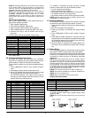
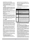
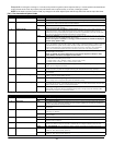
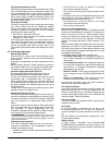
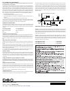
7
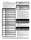
Incorrect connections may result in PTC failure or improper operation.
Inspect wiring and ensure connections are correct before applying power.
Do NOT route any wiring over circuit boards. Maintain at least 1"(25.4mm) separation.
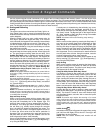
WARNING:
HighVoltage. Disconnect AC Power
and telephone lines before servicing
WARNING:
220 - 240V , 50/60Hz, 200mA
AC
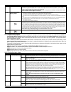
PC5003C Cabinet Shown
Use Model Power UC1 for (2) Battery Installations
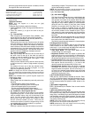
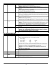
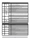
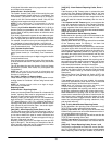
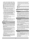
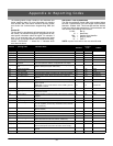
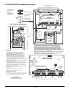
CON1
BAT+BAT-
1.Insert Stand off into cabinet
mounting hole in the desired location.
Snap-in-place.
2.Position circuit board mounting holes
over standoffs. Press firmly on board
to snap-in-place.
IMPORTANT!
Minimum 1/4" (6.4mm) separation
must be maintained at all points between
BATTERY/AC WIRING and all other
wiring connections
FUSE
TB-2
AC AC RED BLK YEL GRN Z1 COM Z2 Z3 COM Z4 Z5 COM Z6 Z7 COM Z8
AUX+ BELL+
AUX- BELL-
PGM1 PGM3
EGND
TIP T-1
PGM2 PGM4
RING R-1
DSC
REV XX
220
UA503
PC-LINK
No.14AWGor smallerconductor
Tye Wraps(not supplied)recommended
InternallyConnected
PC1864
Only
PC1864
PC1832
Only
PC1616/1832/1864
AC in
(Line)
AC in
(Neut)
Transformer
(Neut)
Transformer
(Line)
To EGND on
Control Module
PE
FUSE
12VDC/ 7Ah Battery
PC Board
Cabinet
Stand Off
98431
5
2
TB-2
AC AC RED BLKYEL GRN Z1 COM Z2 Z3 COM Z4 Z5 COM Z6 Z7 COM Z8
AUX+ BELL+
AUX- BELL-
PGM1 PGM3
EGND
TIP T-1
PGM2 PGM4
RING R-1
DSC
REV XX
220
UA503
CON1
BAT+BAT-
PC-LINK
Internally Connected
AUX+ and Keybus (Red) areInternally Connected
Total current draw from Keypads, PGMOutputs and
Aux circuits must notexceed 500ma
PC1864
Only
PC1864
PC1832
Only
6
PC1616/1832/1864
10
16.5V /40VA
AC
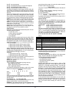
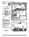
IMPORTANT:
1.This equipment, Alarm Controller PC1616/1832/1864/ETC shall
be installed and used within an environment that provides the
pollution degree max 2 and overvoltages category II
NON HAZARDOUS LOCATIONS, indoor only.The equipment is
FIXED and PERMANENTLY CONNECTED and is designed to be
installed by service persons only; [service person is defined as a
person having the appropriate technical training and experience
necessary to be aware of hazards to which that person may be
exposed in performing a task and of measures to minimize the risks
to that person or other persons.]
2.The connection to the mains supply must be made as per the local
authorities rules and regulations: In the UK as per BS6701.
An appropriate disconnect device must be provided as part of the
building installation.Where it is not possible to rely on identification of
the NEUTRAL in the AC MAINS SUPPLY, the disconnecting device
must disconnect both poles simultaneously (LINE and NEUTRAL).
The device shall disconnect the supply during servicing.
3.The equipment enclosure must be secured to the building structure
before operation.
4.Internal wiring must be routed in a manner that prevents:
- Excessive strain on wire and on terminal connections;
- Loosening of terminal; connections;
- Damage of conductor insulation
5.Disposal of the used batteries shall be made according to the waste
recovery and recycling regulations applicable to the intended market.
6. Before SERVICING, DISCONNECT theTELEPHONE CONNECTION.
See corresponding Section NumberText for wiring details.
7
r.
Do NOT route any wiring over circuit boards. Maintain at least 1"(25.4mm) separation.
WARNING:
HighVoltage. Disconnect AC Power
and telephone lines before servicing
WARNING:
220 - 240V , 50/60Hz, 200mA
AC
PC5003C Cabinet Shown
Use Model Power UC1 for (2) Battery Installations
WWW.DIYALARMFORUM.COM