Set the Printhead and Camera Height 5-13
Caution
Do not allow any part of the gauge to touch the
printheads, and do not leave the gauge on the
platen after setting the head height. If the gauge is
allowed to touch or strike the printheads, the print-
heads could be damaged permanently and require
replacement.
9. Turn the head height adjustment screw clockwise, just until
the end of the gauge slides under the carriage.
Caution
Do not allow the taller surface of the gauge to slide
under the printhead carriage. Damage to the print-
heads or carriage could result.
10. Remove the gauge and repeat steps 7 through 9 at the other
side of the carriage.
11. Verify the heights at both sides of the carriage and adjust if
necessary.
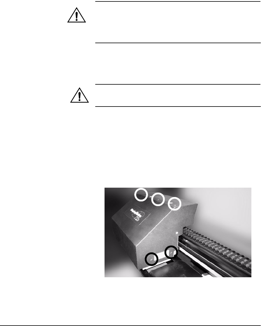
12. Remove the carriage cover.
The carriage cover is attached to the carriage with three
screws at the top, and two screws on each side (see Fig. 5-7
below).
Fig. 5-7. Location of carriage cover screws


