Appendix B Installation of Remote Termination Panels (RTPs) - Digital Input/Digital Output/Analog Output
200 HC900 Hybrid Controller Installation and User Guide Revision 5
9/03
16 Point DC Digital Output
Step Action
1 ATTENTION: RTP and cables are intended for permanent installation within their own enclosure.
ATTENTION: DC Digital Output is rated at 8A per module and 1A per output. Limited to 4A per group
of 8.
Mount RTP cable assembly to HC900 Controller (Figure 60).
• Remove appropriate key tabs from terminal block to allow mating with the module. See page 64.
• Connect desired cable to 16 point DC DO module at controller. Choose from:
900RTC-L010 Remote Terminal Low Voltage Cable Assembly, 1.0 meters long
900RTC-L025 Remote Terminal Low Voltage Cable Assembly, 2.5 meters long.
900RTC-L050 Remote Terminal Low Voltage Cable Assembly, 5.0 meters long
• Install DC DO label into the module connector cover.
• Connect shield drain wire to the grounding bars at the base of the HC900 rack. All field-wiring
shields must be grounded as described in the shield grounding section (page 60).
2 Mount RTP to DIN rail.
• Latch to rail. See page 205.
• Connect cable to RTP
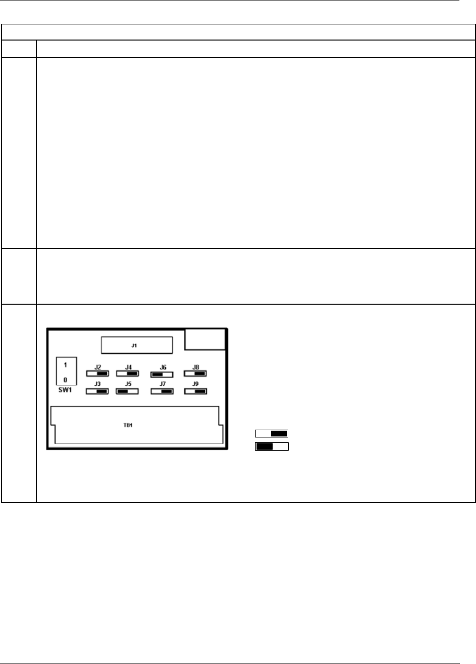
3 Set/verify jumper positions as shown.
Jumper open
Jumper closed
Module Removal / Insertion Under Power (RIUP) is supported by turning off Switch SW1 to allow removal of
the module from the rack without causing an arc. Please see page 62 for more details.
See page 203 for RTP internal schematic.


