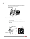
Mobile Base Installation Guide
iii
L
IST
OF
F
IGURES
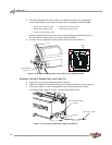
Figure 1-1: Remove the Brake Cover and Hood Clamps . . . . . . . . . . . . . .1-3
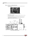
Figure 1-2: Remove the Hood. . . . . . . . . . . . . . . . . . . . . . . . . . . . . . . . . . . .1-4
Figure 1-3: Remove the Temperature Sensor Wires . . . . . . . . . . . . . . . . . .1-4
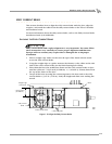
Figure 1-4: Remove the Eddy Current Brake Cables . . . . . . . . . . . . . . . . . .1-5
Figure 1-5: Remove the Eddy Current Brake . . . . . . . . . . . . . . . . . . . . . . . .1-5
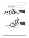
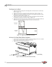
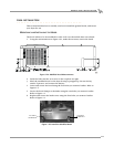
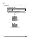
Figure 1-6: Place the Mobile Base Frame on Blocks . . . . . . . . . . . . . . . . . .1-6
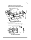
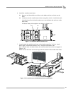
Figure 1-7: Place the Dyno on the Mobile Base Frame. . . . . . . . . . . . . . . .1-6
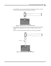
Figure 1-8a: Loosely Attach the Mobile Base Frame to the Dyno . . . . . . .1-7
Figure 1-8b: Loosely Attach the Mobile Base Frame to the Dyno . . . . . . .1-7
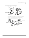
Figure 1-9: Place the Brake on the Mobile Base Frame. . . . . . . . . . . . . . . .1-8
Figure 1-10: Attach the Brake to the Dyno . . . . . . . . . . . . . . . . . . . . . . . . .1-8
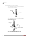
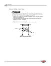
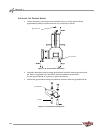
Figure 1-11: Install the Reinforcement Brace. . . . . . . . . . . . . . . . . . . . . . . .1-9
Figure 1-12: Loosely Secure the Mobile Base Frame to the Brake . . . . . . .1-9
Figure 1-13: Install the Wheel to the Rear Wheel Mounting Bracket . . .1-10
Figure 1-14: Install the Wheel to the Front Wheel Mounting Bracket. . .1-10
Figure 1-15: Remove the Existing Bolts . . . . . . . . . . . . . . . . . . . . . . . . . . .1-11
Figure 1-16: Install the Rear Wheel Mount Assemblies. . . . . . . . . . . . . . .1-11
Figure 1-17: Tighten the Mobile Base Frame Bolts . . . . . . . . . . . . . . . . . .1-12
Figure 1-18: Install the Front Wheel Mount Assembly . . . . . . . . . . . . . . .1-12
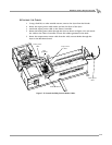
Figure 1-19: Align the Eddy Current Brake . . . . . . . . . . . . . . . . . . . . . . . .1-13
Figure 1-20: Secure the Couplers . . . . . . . . . . . . . . . . . . . . . . . . . . . . . . . .1-14
Figure 1-21: Attach the Eddy Current Brake Cables . . . . . . . . . . . . . . . . .1-15