43-3
Cisco IE 2000 Switch Software Configuration Guide
OL-25866-01
Chapter 43 Configuring Link State Tracking
Link State Tracking
downstream ports changes to the link-down state. Connectivity to server 1 and server 2 is then
changed from link state group1 to link state group 2. The downstream ports 3 and 4 do not change
state because they are in link-group 2.
• If the link state group is configured, link state tracking is disabled, and the upstream interfaces lose
connectivity, the link states of the downstream interfaces remain unchanged. The server does not
recognize that upstream connectivity has been lost and does not failover to the secondary interface.
You can recover a downstream interface link-down condition by removing the failed downstream port
from the link state group. To recover multiple downstream interfaces, disable the link state group.
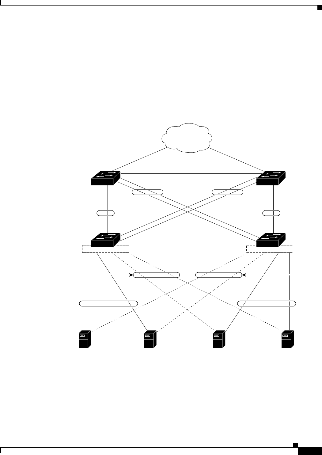
Figure 43-1 Typical Link State Tracking Configuration
Default Link State Tracking Configuration
There are no link state groups defined, and link state tracking is not enabled for any group.
141680
Network
Layer 3 link
Server 1 Server 2 Server 3Server 4
Distribution
switch 1
Distribution
switch 2
Switch A Switch B
Port
1
Port
5
Port
4
Port
3
Port
2
Port
2
Port
3
Port
4
Port
8
Port
7
Port
6
Port
5
Port
1
Port
6
Port
7
Port
8
Link-
state
group 2
Link-state
group 1
Link-state
group 1
Link-state
group 2
Link-state
group 2
Link-
state
group 1
Link-
state
group 1
Primary link
Secondary link
Link-
state
group 2


