QGE 100 • Installation and Maintenance 10
Connecting the Source Computer to the QGE 100
Video data from the source computer is streamed over the network via the QGE 100 to
be viewed on another computer or a Quantum Elite processor. The QGE 100 is compatible
with both digital and analog computer graphics signals.
NOTE: If you do not intend to use keyboard and mouse control of the source
computer through the QGE 100, omit steps 1, 2, 5, and 6 (connecting the
QGE between the source computer and its keyboard and mouse). (See
“Mouse and Keyboard Control of the Source Computer” on page 41 for
more information.)
Connect the QGE to the source computer as follows:
1. Connect one of the provided PS/2 to PS/2 cables between the QGE
mouse PC port (circled at right) and the PS/2 mouse port of the
source computer.
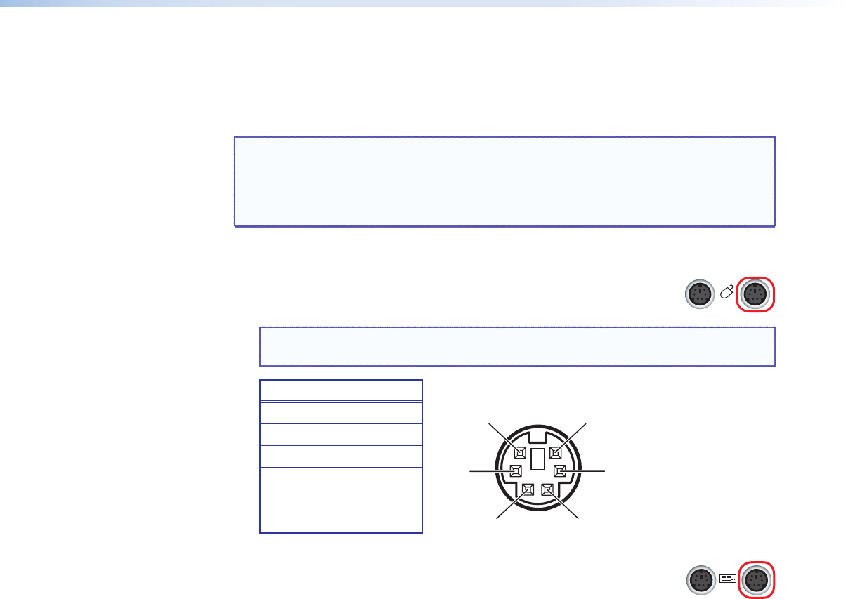
NOTE: The table and illustration below show the pin assignments for all PS/2
connectors on the QGE rear panel.
Pin Function
1 Data
2 No connection
3 Ground
4 +5 V supply
5 Clock
6 No connection
Figure 6. Pin Assignments for Periph and PC Connectors
2. Connect the other PS/2 cable between the QGE keyboard PC port
(circled at right) and the PS/2 keyboard port of the source computer.
3. Connect the appropriate monitor cable between the DVI-I In port on the QGE rear
panel and the source computer monitor port.
• For a digital source computer, connect the provided DVI-I-to-DVI-I cable from
the QGE DVI-I In port to the DVI monitor Out port on the source computer.
• For an analog source computer, connect the provided DVI-A-to-15-pin HD
cable from the QGE DVI-I In port to the analog monitor Out port on the source
computer.
The illustrations and tables on the next page show the pin assignments for the two
DVI-I monitor ports.
PERIPH
PC
1
2
3
4
5


