QGE 100 • Installation and Maintenance 11
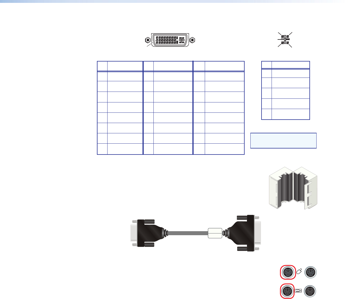
8 Analog V-sync 16 Hot plug detect 24 TMDS clock–
Pin
Signal
Pin Signal
Pin
Signal
1 TMDS data 2– 9 TMDS data 1– 17 TMDS data 0–
2 TMDS data 2+ 10 TMDS data 1+ 18 TMDS data 0+
3 Ground (2/4 ) 11 Ground (1/3) 19 Ground (0/5)
4 TMDS data 4- 12 TMDS data 3- 20 TMDS data 5-
5 TMDS data 4+ 13 TMDS data 3+ 21 TMDS data 5+
6 DDC clock 14 +5 V power* 22 Ground (clock)
7 DDC data 15 Ground (for 5 V) 23 TMDS clock+
1
8
17
24
9
Female DVI Connector
C1
C4
C2
C3
C5
Digital Connections
Analog Connections
Pin
Function
C1
C2
C3
C4
C5
Red signal
Green signal
Blue signal
Horizontal sync
Ground
Analog Portion of DVI Connector
NOTE: Analog vertical
sync is on pin 8.
*Loop-through connection only; 5 V is provided by the source.
4. Important: Clip the provided ferrite block (shown at right)
around the digital or analog monitor cable next to the DVI-A
plug that attaches to the rear panel DVI-I In connector (see
figure 7, below). The ferrite suppresses high frequency noise.
To Source
Computer
To QGE 100
DVI-I Out Port
DVI-A Connector
15-pin HD Connector
Ferrite
Figure 7. Analog Monitor Cable with Ferrite
5. Connect the mouse of the source computer to the Periph mouse
connector on the QGE rear panel (circled at right).
6. Connect the keyboard of the source computer to the Periph
keyboard connector on the rear panel (circled at right).
7. Connect the video monitor of the source computer to the DVI-I Out
port on the QGE rear panel.
• For a digital source computer, connect the DVI source computer monitor
directly to the DVI-I Out port on the QGE rear panel.
• For an analog source computer:
1. Connect the provided DVI-A-to-15-pin HD adapter to the analog source
computer monitor cable.
PERIPH
PC


