186 M208 SPECIFICATIONS: Hardware Specifications
It is important that the settings on the M208’s serial ports are the
same as on the printer’s serial interface.
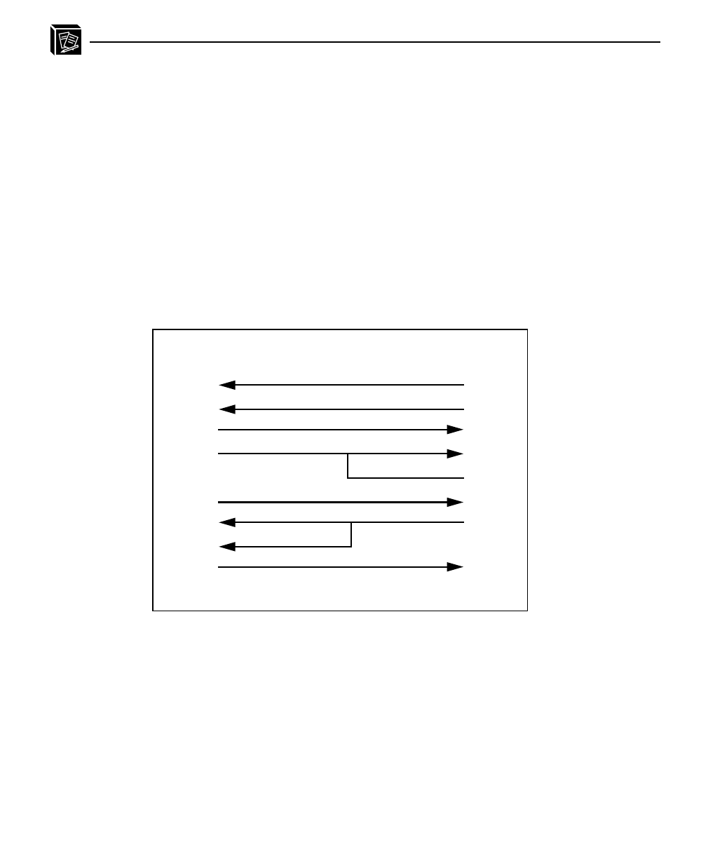
The schematic below shows the most common 9-pin to 25-pin
setup. This setup relies on the DTR signal meaning that the
printer must toggle DTR if it can or cannot take more data. If the
printer uses another signal to do this, this schematic will not
work. The key to hardware flow control working then is to know
what signal the printer toggles when it is able to take more data
and once you know this, you can make this signal go to the CTS
pin (Pin 8) on the M208’s serial interface.
Sometimes devices are attached to the M208’s serial ports that
have 9-pin connectors (e.g. a PC attached to the serial port for
configuration purposes). When choosing the correct 9-pin to 9-
pin cable for this, the key pins are 2 and 3 on both ends which
must relate to transmit and receive. Transmit on one side must
always go to receive on the other and vice versa or else there will
be no communications between the two devices.
o
e
Serial Cable Schematic
M208
9-pin F
DTE
25-pin M
1
2
3
4
5
6
8
7
4
2
3
5
6
7
20
8
Typical 9-pin to 25-pin RS-232C cable
o
e


