Appendix A: Specifications
184
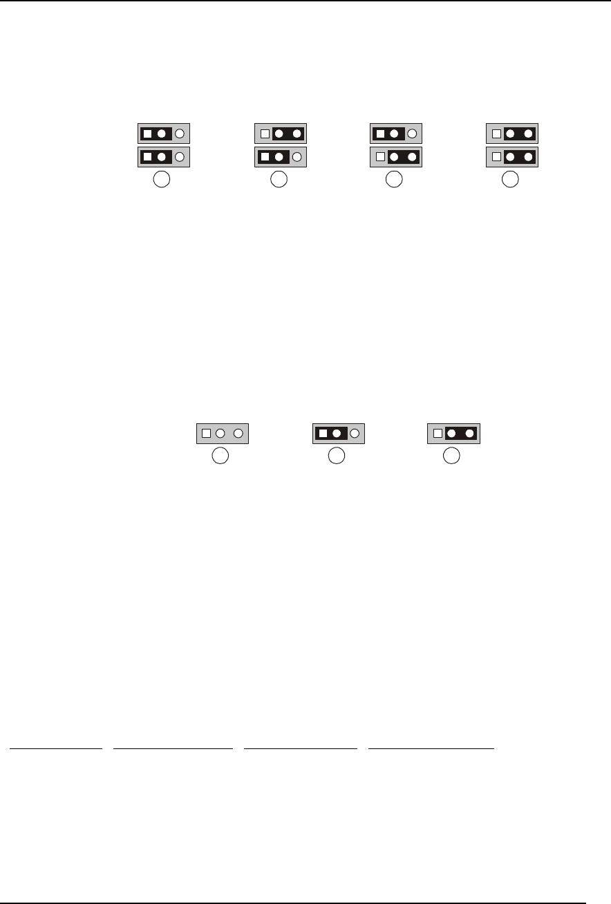
Forcing a Firmware Update and Flashing Bootblock Write Enable
Jumper blocks J4E1 and J4E2 allow you force a firmware update and flash bootblock write enable.
By default, both these features are disabled.
1
1
A
1
1
B
1
1
C
1
1
D
J4E2
J4E1
J4E2
J4E1
J4E2
J4E1
J4E2
J4E1
Figure A-25. Firmware Update and Flash Bootblock Write Enable Jumpers
Jumper setting labeled:
A. No Firmware Update or Flash Bootblock Enable (Default Setting)
B. Flash Bootblock Enable
C. Force a Firmware Update
D. Force a Firmware Update and Flash Bootblock Enable
Configuring Brownout Protection
Jumper block J4D1 provides the ability to set the brownout protection for either 110 or 220 Volts. By
default, 110 Volt protection is enabled.
1
A
J4A1
1
B
J4A1
1
C
J4A1
Figure A-26. Brownout Protection Jumpers
Jumper setting diagram labeled:
A. Low Line for 110 Volt Brownout Protection (Default Setting)
B. Low Line for 110 Volt Brownout Protection (Default Setting)
C. High Line for 220 Volt Brownout Protection
Determining DC-to-DC Status
Each DC-to-DC has an LED that indicates whether power is supplied to the DC-to-DC and the health
of the DC-to-DC. Table A-15 provides more detail on the LEDs. The LEDs are located on the
Sideplane board above the 5-Volt DC-to-DC connector (J6B1).
Table A-15. DC-to-DC LED
AC Power not
Present
Amber LED
AC Power Present
System Powered
Off Amber LED
AC Power Present
System Powered
On Amber LED
Description
OFF No AC power to any
power supply or DC-
to-DC
ON AC present / Standby
output on


