Chapter 5: Installing Additional Memory
37
Removing the Processor/Memory Complex
The Processor/Memory Complex mounts memory boards to the processor board and forms a module
that you can remove from the main system chassis. To access this module, you need to remove the
access door on the side of the chassis and remove the four screws on the left side of the chassis to
slide the Processor/Memory Complex out of the system.
1. If the system is already installed and working, power down the system. Refer to Chapter 1,
"Controls, Ports, and Indicators."
WARNING The power supply will continue to provide standby current to the HP Server until
the power cable is disconnected. Before removing the cover, always disconnect
the power cord and unplug the Ethernet cables. Disconnect the power cord to
avoid exposure to high energy levels that may cause burns when parts are short-
circuited by metal objects such as tools or jewelry.
2. Disconnect the power cables and any external cables connected to the system.
If necessary, label each cable to expedite re-assembly.
WARNING Make sure that the rack is anchored securely so that it does not tip when the server
is extended from the rack.
3. Pull the chassis out of the rack to expose the Processor/Memory Bay on the right side of the
chassis as you face its front.
4. Remove the four screws that secure the complex to the chassis. These screws are located on
the left side of the chassis as you face the front of the system.
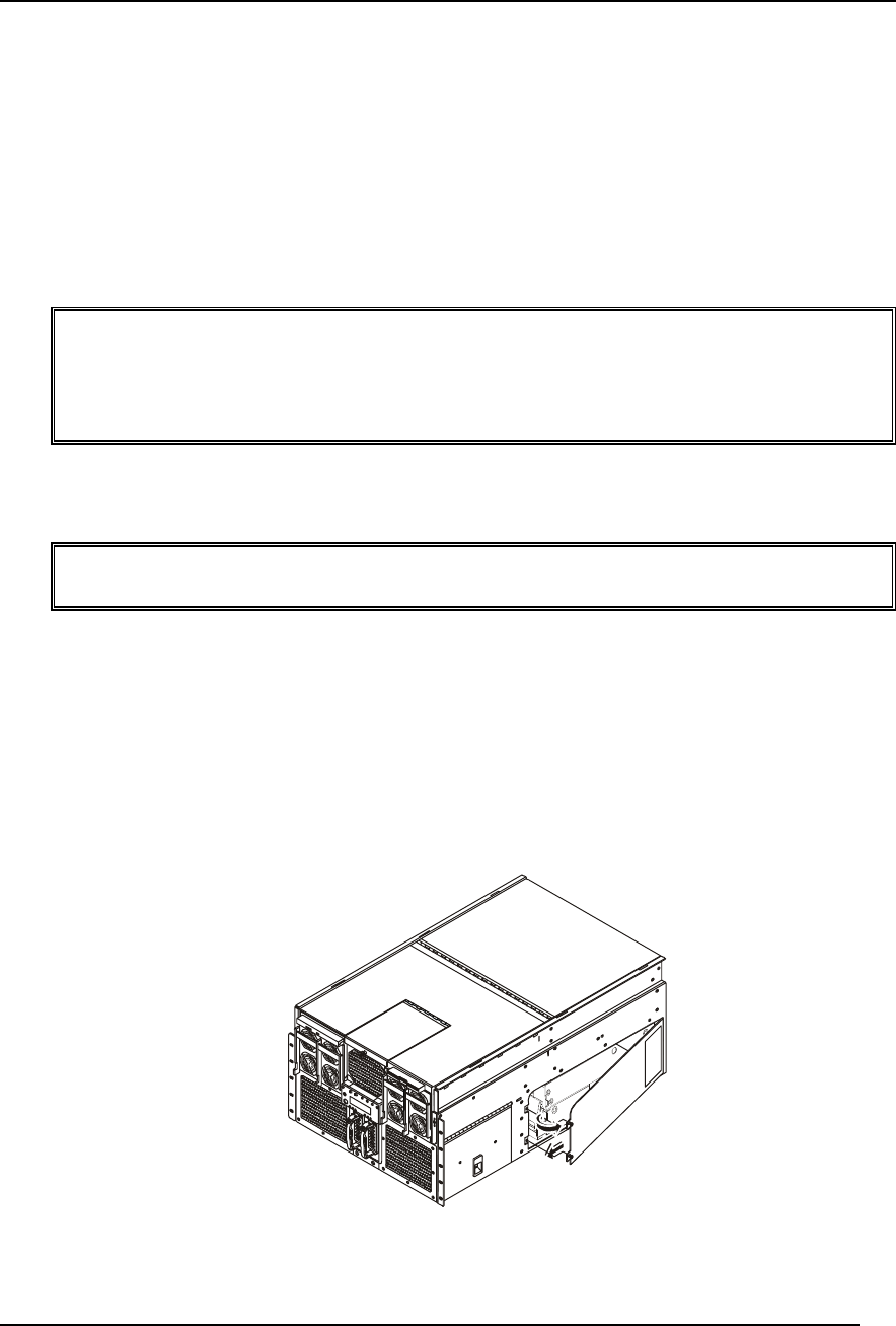
5. Loosen the two-quarter turn screws on the left side of the Processor/Memory Complex cover
such that the cover springs open.
6. Grasp the cover and press it back toward the chassis as you shift the cover to the left. Shifting
the cover to the left clears the right side of the cover from behind the chassis side.
3
Figure 5-1. Opening the Processor/Memory Complex Bay Cover
7. Once the cover is clear, set it aside.


