Chapter 8: Server Management
71
Sideplane Board
The Sideplane is attached inside the left wall at the rear of the chassis. It receives the I/O Baseboard
as well as the Power Distribution Board (T-Docking). To remove the Sideplane you must remove the
Power Distribution Board (T-Docking), the I/O Baseboard, and the Processor/Memory Complex.
Removing the Sideplane Board
To remove the Sideplane board, complete the following procedure:
1. Observe all safety and ESD precautions for handling electronic components.
2. Remove the I/O Baseboard as described in “Removing the I/O Baseboard” in this chapter.
3. Remove the Power Distribution Board (T-Docking) as described in “Removing the Power
Distribution Board (T-Docking)” in this chapter.
4. Remove the Processor/Memory Complex as described in “Removing the Processor/Memory
Complex” in Chapter 5.
a) Remove the sheet-metal cover protecting the D2D converts on the sideplane board.
b) Remove the D2D converters from the sideplane board.
NOTE Do not remove the screws that hold the Sideplane to the mounting plate.
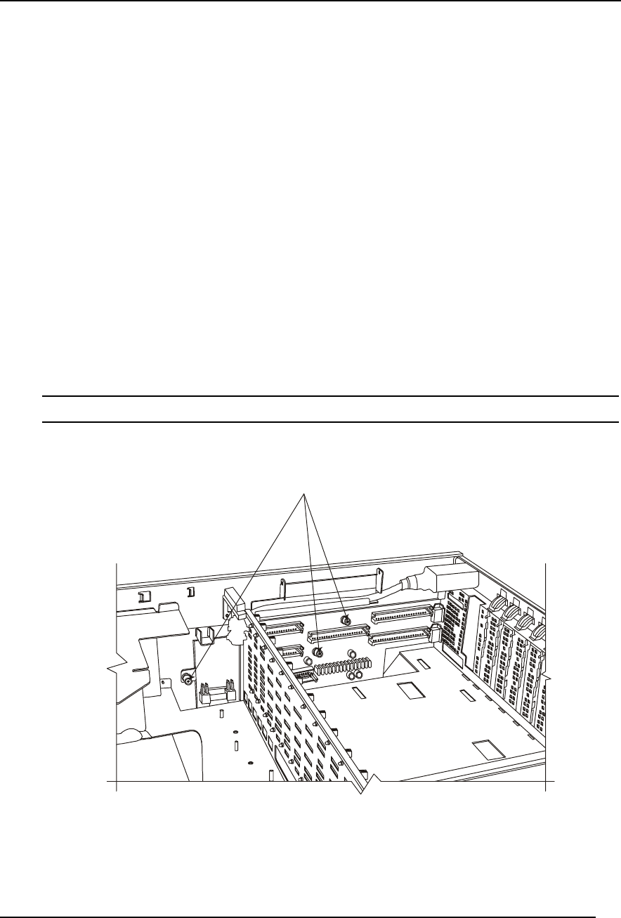
5. Loosen the captive thumbscrews on the Sideplane that secure it and its mounting plate to the
chassis.
Loosen the three captive thumb screws.
Figure 8-4. Removing the Screws from the Sideplane
6. Slide the Sideplane towards the front of the chassis. As you slide the board, keep the front
bottom edge of the board in contact with the carrier tray as the board is rotated up and out of
the chassis.


