KeypadLinc Schedule Timer Owner’s Manual
Page 10 of 26
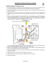
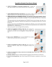
6) Connect the KeypadLinc Secondary’s GROUND Wire. Connect the
bare copper GROUND wire to the other GROUND wire in the junction box.
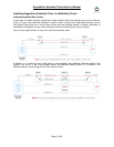
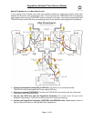
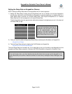
7) Install additional KeypadLinc Secondaries. If you have a 4-way or greater switching circuit, see
Special Treatment for 4- or More-Way Circuits at the end of this section.
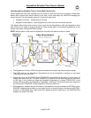
8)
Identify the wires for the KeypadLinc Primary. The KeypadLinc Primary is the KeypadLinc that will
actually control the load. In the junction box where you will install the KeypadLinc Primary, find the
wire that carries power from the switch to the lights. This wire, called the LOAD wire, is commonly
red.
In the same junction box, there will also be the two TRAVELER wires from the first box, often both in the
same cable sheath. Identify the TRAVELER wire (black) that you connected the LINE wire to in the first
junction box.
If you’re not sure which is the TRAVELER wire connected to the LINE wire, you can use the same method
described in step 1 to find it. Turn on the power (taking the same precautions) and use a voltmeter to find
the wire with 110 – 120 Volts AC on it.
Make sure the power is turned off again before proceeding.
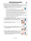
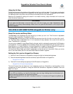
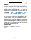
9) Connect the KeypadLinc Primary’s LINE wire. Use a wire nut to
connect the TRAVELER wire (usually black)
connected to the LINE wire to the KeypadLinc Primary’s black LINE
wire.
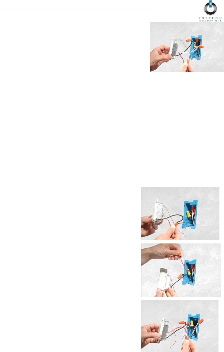
10) Cap the other TRAVELER wire. The other TRAVELER wire (usually
red) will not be used, so put a wire nut on the end of it.
11) Connect the KeypadLinc Primary’s LOAD wire. Use a wire nut to
connect the LOAD wire (usually red) to the KeypadLinc Primary’s red
LOAD wire.
12) Connect the KeypadLinc Primary’s NEUTRAL and GROUND wires. Repeat steps 5 and 6 with the
KeypadLinc Secondary.
13) Complete installation. Return to Installing KeypadLinc Schedule Timer and continue on from step 5.
14) Cross-Link the KeypadLincs. See Cross-Linking INSTEON Devices to complete the virtual 3-way
circuit.