KeypadLinc Schedule Timer Owner’s Manual
Page 6 of 26
Installing KeypadLinc Schedule Timer
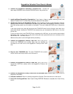
1) At the circuit breaker or fuse panel, disconnect the power for all of the circuits in the switch junction
box. Verify that the power is off by trying to turn on the lights controlled by the switches.
2) Remove the wallplate from the switch you are replacing. Then, unscrew the switch itself and pull it out
from the junction box.
3) Disconnect the wires from the switch you are replacing. If the wires cannot be detached by
unscrewing them, cut the wires where they enter the switch, and then strip ½ inch of insulation off the
ends.
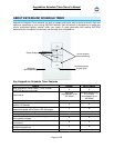
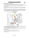
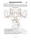
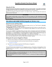
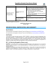
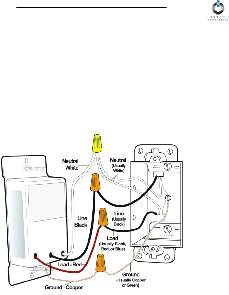
4) If you are installing KeypadLinc into a standard 2-way circuit (where only one switch controls the
load), follow the diagram below to identify and connect the LINE, LOAD, NEUTRAL, and GROUND
wires on KeypadLinc. Be sure you have correctly identified the wires in the switch junction box before
connecting them. See Identifying the Electrical Wires in your Home.
Wiring Diagram
NOTE: Home’s wire color and wire location may vary
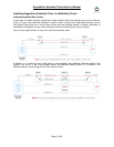
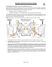
If you are installing KeypadLinc into a multi-way circuit (where more than one switch controls the
load), see Installing KeypadLinc Schedule Timer in a Multi-Way Circuit.
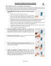
5) After you have connected all of the wires, ensure that the wire connectors are firmly attached and that
there is no exposed copper except for the GROUND wire
6) Gently place KeypadLinc into the junction box, orienting the unit with the Set button on the bottom,
and screw into place
7) Enable power to the switch from the circuit breaker or fuse panel
8) Test that KeypadLinc is working properly by tapping its On and Off buttons
9) Reinstall the wallplate