KeypadLinc Schedule Timer Owner’s Manual
Page 8 of 26
Using KeypadLinc Schedule Timer in Virtual Multi-Way Circuits
Once KeypadLincs have been installed, you can create a virtual multi-way circuit to control a single load.
Rather than connect each switch directly to the load, virtual multi-ways use INSTEON messaging to
control the load. Two components make up a virtual multi-way circuit:
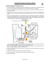
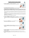
• KeypadLinc Primary – wired directly to the load
• KeypadLinc Secondaries – other KeypadLincs in the circuit, but not wired to the load
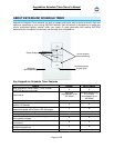
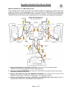
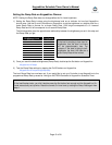
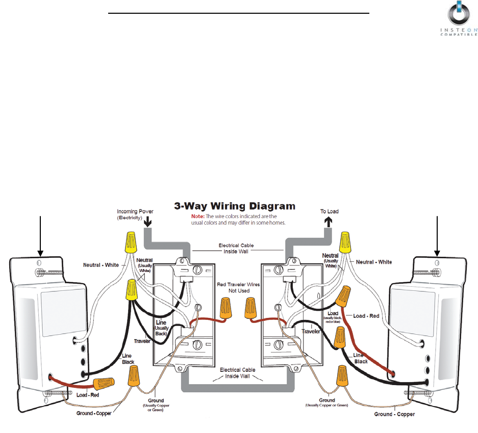
The diagram below shows how to wire a 3-way circuit with two KeypadLincs. After the KeypadLincs have
been wired-in, you create a virtual multi-way by Cross-Linking each of the desired KeypadLincs to one
another (see Cross-Linking INSTEON Devices).
NOTE: Actual location of the wires on KeypadLinc may differ with device revision or model.
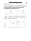
• The KeypadLinc Primary’s LOAD wire gets connected to the actual load that is being controlled
• The LOAD wire for any KeypadLinc Secondaries will not be connected to anything, so cap those
LOAD wires off with a wire nut
• Notice that one of the TRAVELER wires (TRAVELER 1, the red one) is not used, so you will cap it off
at both ends with a wire nut. The other TRAVELER (TRAVELER 2, the black one) you will convert to
a LINE wire. In the junction box where the KeypadLinc Secondary is, connect TRAVELER 2 to the
existing LINE and also to the KeypadLinc Secondary’s LINE wire. In the junction box at the other end,
you will connect TRAVELER 2 to the KeypadLinc Primary’s LINE wire.
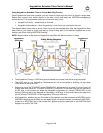
• All KeypadLincs, whether they are Primaries or Secondaries, must be connected to NEUTRAL and to
GROUND. Note that the switches you are replacing will not normally have a connection to NEUTRAL.
If there is no NEUTRAL wire in the junction box, please consult an electrician or call INSTEON Gold
Support Line at 800-762-7845.
Primary
Secondary