Page 17
Cumberland Gap Wood Stove
R
November 5, 2010
7006-188G
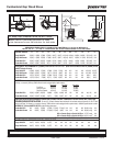
Items Needed for Installation: 4 in. (102mm) diameter fl ex
pipe in the length as required for your installation; Phillips
screwdriver; Silicone sealant; Drills and saws necessary for
cutting holes through the wall or fl ooring in your home.
Included in Kit: 2 cable ties; oustide air termination cap;
mounting screws (Discard the remaining parts).
NOTE: If you plan to install the optional blower AND the
outside air kit, complete installation of the outside
air kit FIRST.
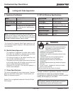
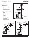
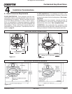
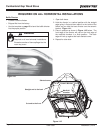
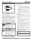
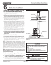
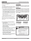
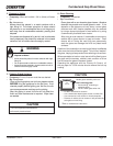
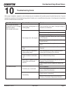
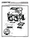
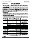
REAR SHIELD
BLOWER MOUNTING
FLANGE
BLOWER SPEED CONTROL
BLOWER
MOUNTING
FLANGE
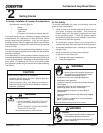
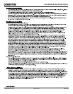
REAR
SHIELD
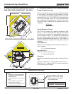
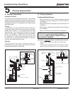
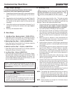
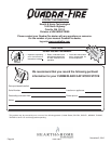
OUTSIDE AIR
TERMINATION CAP
(contains rodent screen)
OUTSIDE AIR
INTAKE
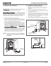
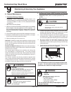
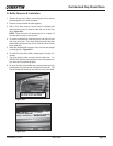
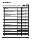
1. Remove all materials from packing box.
2. Mount the fl ex fl ange (with pipe fi tting extending out),
over the intake air opening at the rear of stove using
the four mounting screws supplied with kit.
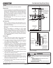
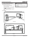
3. Cut a 4 inch (102mm) minimum hole in the fl oor or wall
to accommodate outside air piping. Use 4 inch (102mm)
metal fl ex or rigid piping to directly connect outside air
to the unit or into vented crawl space. (Do not put fl ex
into a non-vented crawl space).
If using fl ex tubing attach cable ties to secure tubing
at both ends. Use the supplied termination cap with a
rodent screen. Seal between the fl oor or wall and the
pipe with silicone to prevent moisture penetration.
Figure 17.1
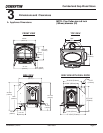
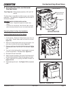
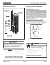
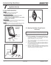
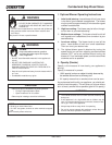
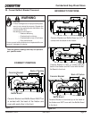
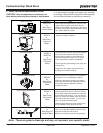
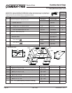
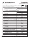
1. Remove 3 phillips head screws from rear of stove.
2. Using the phillips head screws, attach blower to lower
rear of stove, as shown.
3. Plug blower cord into a grounded outlet. Do not remove
ground prong from plug. Route power cord to avoid
heat from the stove, or other damage. Do not route
cord under or in front of appliance.
4. Adjust the blower speed control to the desired speed.
H. Installation Of Optional Blower
The blower is shipped fully assembled and ready for
installation.
G. Outside Air Kit Installation
Figure 17.2
Figure 17.3