Printer and Troubleshooting Overview 1-7
Error Code Technical Definitions
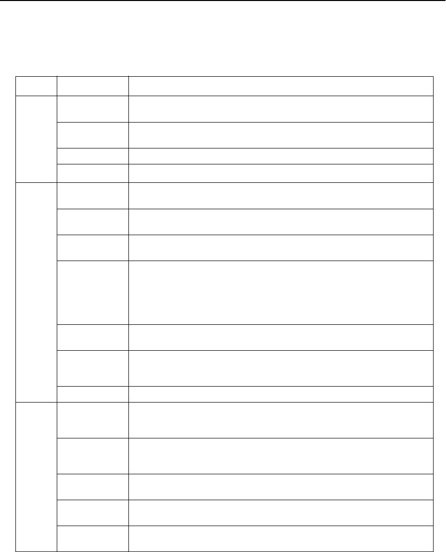
The following table lists the printer error codes and their descriptions.
Table 1-1. Error Code Technical Definitions
Type Error Description
Cassette Errors
010, E10 PCL board detected no signal from upper paper cassette empty
sensor indicating no paper present
011 PCL board detected no signal from lower paper cassette empty
sensor indicating no paper present
012, E12 PCL board detected no signal from upper cassette in switch
013 PCL board detected no signal from lower cassette in switch
Paper Jams in the Primary Paper Path
020 PCL board detected that the paper being fed from the upper cas-
sette did not reach the timing paper sensor within the allotted time
021 PCL board detected that the paper being fed from the lower cas-
sette did not reach the timing paper sensor within the allotted time
022 PCL board detected that the exit paper sensor did not activate or
the timing sensor did not deactivate within the allotted time
023 PCL board detected that either:
1. The exit paper sensor (within the printer) became activated but
did not deactivate within the specified time.
2. (HCO only). The paper exit sensor (within the HCO) did not
become activated or deactivated within the allotted time
025 PCL board detected that the timing paper sensor was activated
immediately after one of the covers was closed
026 PCL board detected that either the exit paper sensor (within the
printer) or the paper exit sensor (within the HCO) was activated
immediately after one of the covers was closed
027 PCL board detected paper in the duplex area after clearing a jam
Toner Control Errors
030 PCL board detected a signal from the high-voltage power supply
unit indicating an abnormal load on the bias voltage to either the
developer unit, cleaner unit, or printhead-cleaning bias plates.
031 PCL board detected a signal from the toner patch sensor board
indicating that the reference voltage level on the photoconductor
was too low.
032 PCL board detected a signal from the toner patch sensor board
indicating that the toner patch on the photoconductor was too light.
035 PCL board detected too many successive signals from the toner
patch sensor board for a toner feed.
036 PCL board detected no developer unit electrical interlock signal
from the J25 connector.


