KP915GV Product Manual
113
1 Timer is enabled and counting
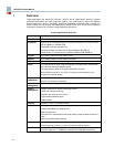
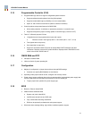
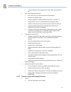
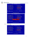
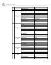
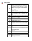
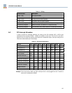
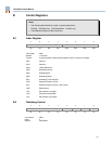
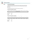
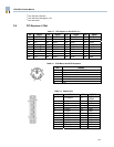
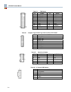
B.5 Watchdog Timeout Period
7 6 5 4 3 2 1 0
Watchdog timeout period
R/W R/W R/W R/W R/W R/W R/W R/W
I/O location: 066h
Index 1
Default: 11111111b
Timeout period
0 Do not use (causes immediate timeout)
1–255 Timeout period in units of 1 x prescale value seconds
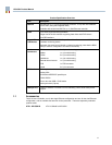
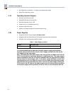
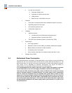
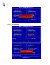
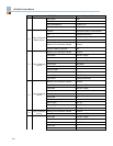
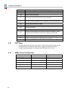
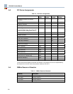
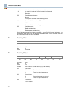
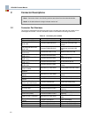
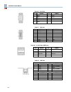
B.6 General Purpose I/O Port 1
7 6 5 4 3 2 1 0
PI7 PI6 PI5 PI4 PI3 PI2 PI1 PI0
R/W R/W R/W R/W R/W R/W R/W R/W
I/O location: 066h
Index: 2
Default: 00000000b
P17–P10, GPIO Port 1 data:
When programmed as an output, the GPIO port 1 bit follows the value written into this register and
reads reflect the value written.
When programmed as inputs, writes are ignored and a read follows the state of the GPIO port 1
signal. Direction control is via the GPIO port 2 and control register.
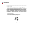
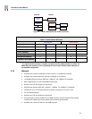
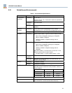
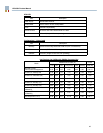
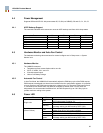
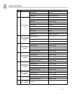
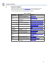
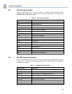
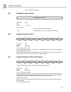
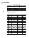
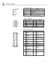
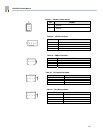
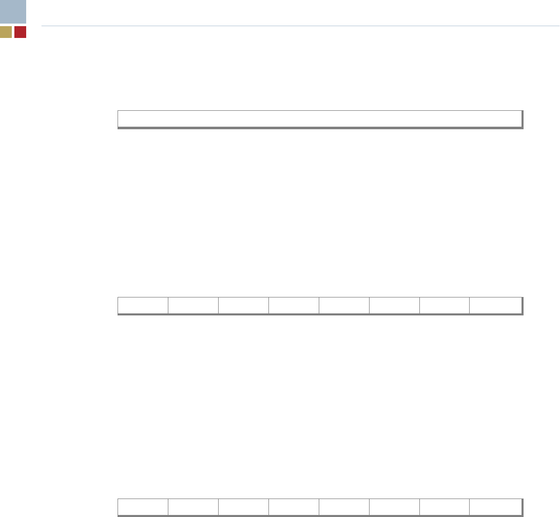
B.7 General Purpose I/O Port 2 and Control
7 6 5 4 3 2 1 0
D201 D157 D104 P24 P23 P22 P21 P20
R/W R/W
R/W
9
R/W R/W R/W R/W R/W
9
Controller versions up to and including 2 do not support reading this bit
I/O location: 066h
Index: 3
Default: 00000000b
P21 – P20, GPIO Port 2 data:
When programmed as an output, the GPIO port 2 bit follows the value written into this register and
reads reflect the value written. When programmed as inputs, writes are ignored and a read follows
the state of the GPIO port 2 signal. Direction control is via the D201 control.
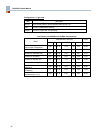
P22, GPIO Port 2 data:
This bit is output only. GPIO port 2 bit 2 follows the value written into this register and reads reflect
the value written.
P24 - P23, GPIO Port 2 data: