KP915GV Product Manual
39
• Greater than 100 years Data Retention
• Low Power Consumption
• Active Read Current: 6 mA (typical)
• Standby Current: 10 µA (typical)
• Fast Sector-Erase/Byte-Program Operation
• Sector-Erase Time: 18 ms (typical)
• Block-Erase Time: 18 ms (typical)
• Chip-Erase Time: 70 ms (typical)
• Byte-Program Time: 14 µs (typical)
• Chip Rewrite Time: SST49LF004B: 8 seconds (typical)
• Single-pulse Program or Erase
• Internal timing generation
• Two Operational Modes
• Low Pin Count (LPC) interface mode for in-system operation
• Parallel Programming (PP) mode for fast production programming
• LPC Interface Mode
• LPC bus interface supporting byte Read and Write
• 33 MHz clock frequency operation
• WP# and TBL# pins provide hardware write protect for entire chip and/or top Boot
Block
• Block Locking Registers for individual block write-lock and lock-down protection
• JEDEC Standard SDP Command Set
• Data# Polling and Toggle Bit for End-of-Write detection
• 5 GPI pins for system design flexibility
• 4 ID pins for multi-chip selection
• Parallel Programming (PP) Mode
• 11-pin multiplexed address and 8-pin data I/O interface
• Supports fast In-System or PROM programming for manufacturing
• Packages 32 pin lead PLCC (10mm x 20mm)
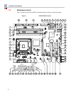
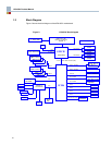
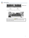
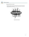
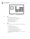
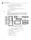
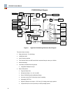
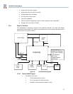
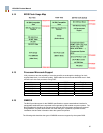
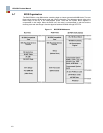
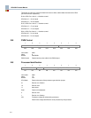
3.3 Major Sub-systems
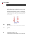
3.3.1 Audio Interface
The motherboard includes High Definition integrated audio function support, using the ICH6
integrated audio controller and a SigmaTel STAC9200. The STAC9200 is a high quality, 2-channel
audio codec compatible with the Intel High Definition (HD) Audio Interface. The STAC9200 provides
Stereo 24-Bit resolution with sample rates up to 192kHz. The STAC9200 incorporates SigmaTel's
proprietary SD technology to achieve an estimated DAC SNR in excess of 100dB. See Figure 8.