KP915GV Product Manual
93
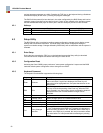
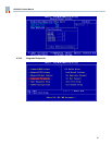
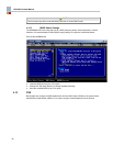
4.4 Power Management
Supports APM and ACPI 2.0 with power states S0, S3, S4 (not S4BIOS), S5 and C0, C1, C2, C3.
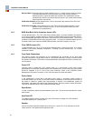
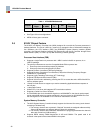
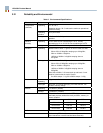
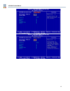
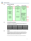
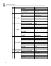
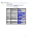
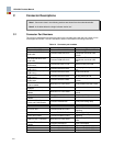
4.4.1 ACPI Wake-up Support
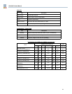
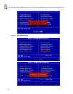
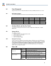
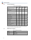
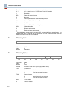
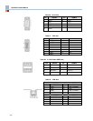
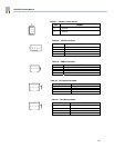
The next table indicates which events can cause an ACPI wake-up and from which sleep states.
Event S1 S3 S4 S5
Power Switch v v v v
RTC alarm v v v v
PS2 Mouse/Keyboard v
USB Device v v
PME v v v v
WOL v v v v
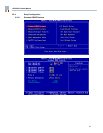
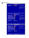
4.5 Hardware Monitor and Auto Fan Control
The hardware monitoring values and auto fan control configure was in 'Setup menu -> System
Monitor' item.
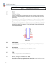
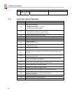
4.5.1 Hardware Monitor
The LM96000 measures:
• Temperature of two remote diodes and its own die.
• VCCP, 3.3VSBY, 5.0V, and 12V.
• 3 fan tachometer inputs.
• Lithium Cell Battery Voltage
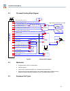
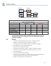
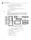
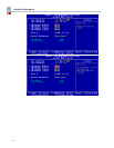
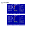
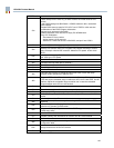
4.5.2 Automatic Fan Control
In Auto Fan Mode, the LM96000 will automatically adjust the PWM duty cycle of the PWM outputs.
PWM outputs are assigned to a thermal zone based on the fan configuration registers. It is possible
to have more than one PWM output assigned to a thermal zone. For example, PWM outputs 2 and
3, connected to two chassis fans, may both be controlled by thermal zone 2. At any time, the
temperature of a zone exceeds its absolute limit, all PWM outputs will go to 100% duty cycle to
provide maximum cooling to the system.
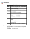
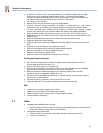
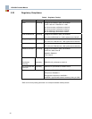
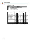
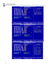
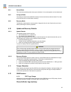
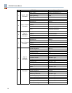
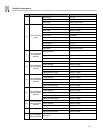
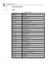
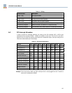
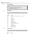
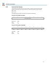
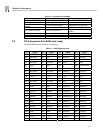
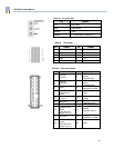
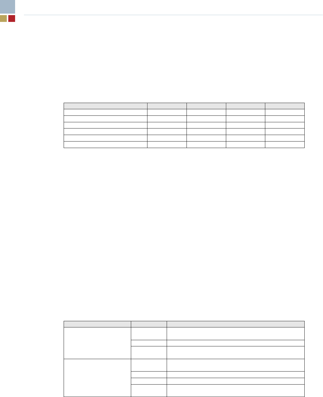
4.6 Power LED
LED State Indicates
OFF
The motherboard is powered down or in one of the
ACPI sleep states (including S1).
ON The motherboard is fully powered up (S0).
Single color
Blinking
The motherboard is fully powered up (S0) with a
message waiting (as determined by ACPI TAPI).
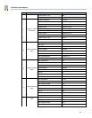
OFF
The motherboard is powered down or in ACPI sleep
states S4 or S5 (no +5V supply available)
Green The motherboard is fully powered up (S0).
Yellow The motherboard is in sleep state S1.
Dual Color
(Green /Yellow)
Blinking
green
The motherboard is fully powered up (S0) with a
message waiting (as determined by ACPI TAPI).