KP915GV Product Manual
114
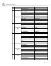
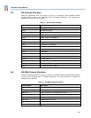
These bits are input only. Writes to these bits have no effect; reads reflect the state of the GPIO
port 2 bits 4 and 3 respectively.
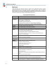
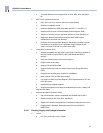
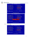
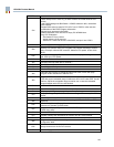
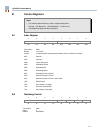
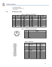
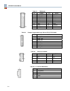
D104, GPIO Port 1 bits 0 – 4 direction control:
GPIO bits 10 – 14 are inputs
GPIO bits 10 – 14 are outputs
D157, GPIO Port 1 bits 5 – 7 direction control:
GPIO bits 15 – 17 are inputs
GPIO bits 15 – 17 are outputs
D201, GPIO Port 2 bits 0 – 1 direction control:
GPIO bits 20 – 21 are inputs
GPIO bits 20 – 21 are outputs
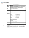
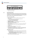
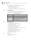
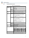
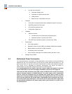
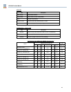
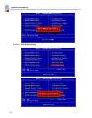
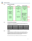
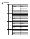
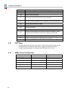
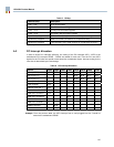
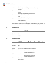
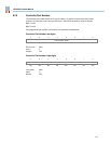
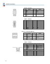
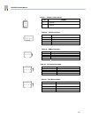
B.8 PWM Control
7 6 5 4 3 2 1 0
Reserved PWM control
R/W R/W R/W R/W R/W R/W R/W R/W
I/O location: 066h
Index: 8
Default: 00000000b
PWM Control Determines the pulse width of the PWM output.
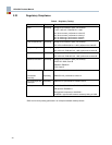
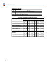
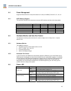
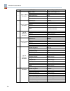
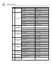
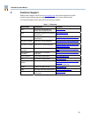
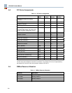
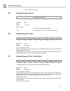
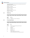
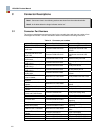
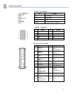
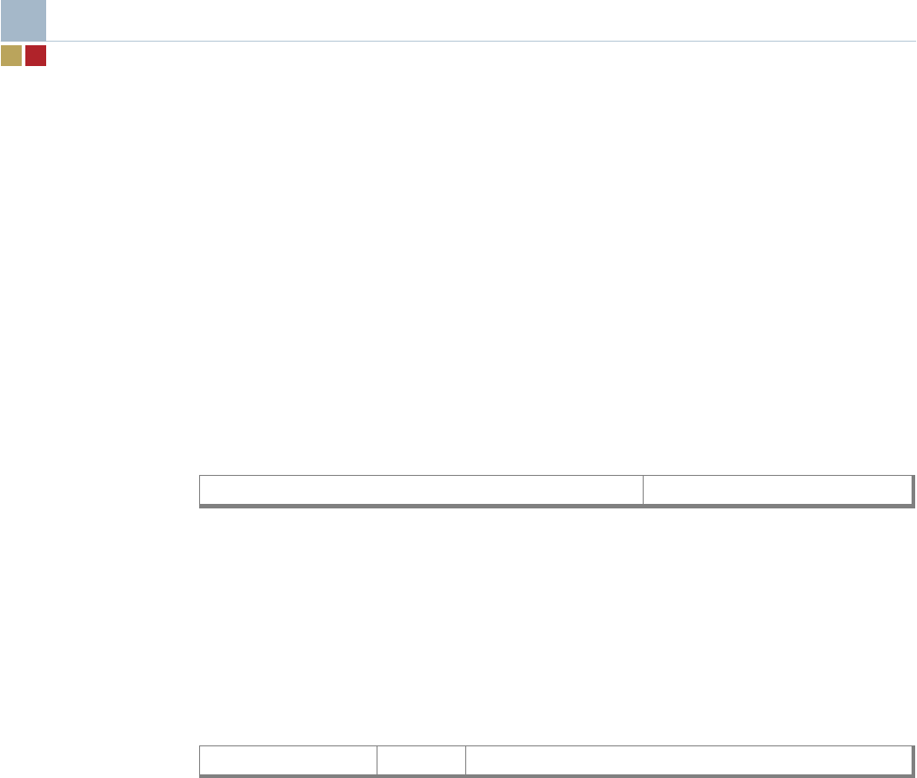
B.9 Processor Identification
7 6 5 4 3 2 1 0
CPU mode P4M Voltage ID, VID4–VID0
RO RO RO RO RO RO RO RO
I/O location: 066h
Index: 10
Default: N/A
CPU Mode Returns the state of the processor type selection jumper:
01 Pentium 4 or Celeron
10 Pentium 4-M
11 Auto select
P4M Pentium 4-M detected:
0 Pentium 4-M
1 Pentium 4 or Celeron
VID Processor voltage ID (selected by processor):
Returns the voltage identification value presented by the processor.